Nondestructive Testing

Nondestructive testing (NDT) is a wide group of analysis techniques used in science and technology industry to evaluate the properties of a material, component or system without causing damage. The terms nondestructive examination (NDE), nondestructive inspection (NDI), and nondestructive evaluation (NDE) are also commonly used to describe this technology. Because NDT does not permanently alter the article being inspected, it is a highly valuable technique that can save both money and time in product evaluation, troubleshooting, and research.
  • Nondestructive Testing (NDT)
  • RADIOGRAPHIC TEST (RT)+

    Industrial radiography is a method of non-destructive testing where many types of manufactured components can be examined to verify the internal structure and integrity of the specimen. Industrial Radiography can be performed utilizing either X-rays or gamma rays. X and gamma rays have the shortest wavelength and this property leads to the ability to penetrate, travel through, and exit various materials such as carbon steel and other metals.

    Gamma radiation sources, most commonly iridium-192 and cobalt-60, are used to inspect a variety of materials. The vast majority of radiography concerns the testing and grading of welds on pressurized piping, pressure vessels, high-capacity storage containers, pipelines, and some structural welds. Other tested materials include concrete, welder's test coupons, machined parts, plate metal, or pipe-wall (locating anomalies due to corrosion or mechanical damage). Non-metal components such as ceramics used in the aerospace industries are also regularly tested.
  • ULTRASONIC TESTING (UT)+

    Ultrasonic testing (UT) is a family of non-destructive testing techniques based on the propagation of ultrasonic waves in the object or material tested. In most common UT applications, very short ultrasonic pulse-waves with center frequencies ranging from 0.1-15 MHz, and occasionally up to 50 MHz, are transmitted into materials to detect internal flaws or to characterize materials. A common example is ultrasonic thickness measurement, which tests the thickness of the test object, for example, to monitor pipework corrosion and ultrasonic testing for weldment.

    Ultrasonic testing is often performed on steel and other metals and alloys, though it can also be used on concrete, wood and composites, albeit with less resolution. It is used in many industries including steel and aluminium construction, metallurgy, manufacturing, aerospace, automotive and other transportation sectors.

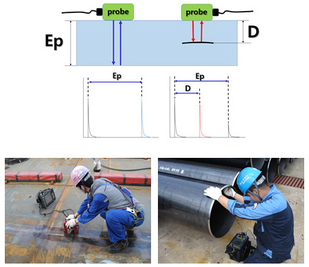
    Principle of ultrasonic testing. LEFT. A probe sends a sound wave into a test material. There are two indications, one from the initial pulse of the probe, and the second due to the back wall echo. RIGHT: A defect creates the third indication and simultaneously reduces the amplitude of the back wall indication. The depth of the defect is determined by the ratio D/Ep
  • PHASED ARRAY ULTRASONIC TESTING (PAUT)+

    The PA probe consists of many small ultrasonic transducers, each of which can be pulsed independently. By varying the timing, for instance by making the pulse from each transducer progressively delayed going up the line, a pattern of constructive interference is set up that results in radiating a quasi-plane ultrasonic beam at a set angle depending on the progressive time delay. In other words, by changing the progressive time delay the beam can be steered electronically. Phased array is widely used for nondestructive testing (NDT) in several industrial sectors, such as construction, pipelines, and power generation. This method is an advanced NDT method that is used to detect discontinuities i.e. cracks or flaws and thereby determine component quality. Due to the possibility to control parameters such as beam angle and focal distance, this method is very efficient regarding the defect detection and speed of testing. Apart from detecting flaws in components, phased array can also be used for wall thickness measurements in conjunction with corrosion testing.
  • TIME OF FLIGHT DIFFRACTION (TOFD)+

    TOFD method of ultrasonic testing is a sensitive and accurate method for the nondestructive testing of welds for defects. The use of TOFD enabled crack sizes to be measured more accurately, so that expensive components could be kept in operation as long as possible with minimal risk of failure. TOFD is summarized as tip-diffraction techniques which utilized the principle that the tips of a crack when struck by a wave will diffract the signals back to the other location on the surface.
    A TOFD setup with transmit and receive probes. In this case the receive
    probe sees four indications: one from the lateral wave that has travelled along the upper surface, one from the wave that has reflected off the far surface, and two from the defect in the test object. When a crack is present, there is a diffraction of the ultrasonic wave from the tip(s) of the crack. Using the measured time of flight of the pulse, the depth of a crack tips can be calculated automatically by simple trigonometry.
  • PENETRANT TESTING (PT)+

    Penetrant Testing (PT), is a widely applied and low-cost inspection method used to check surface-breaking defects in all non-porous materials (metals, plastics, or ceramics). The penetrant may be applied to all non-ferrous materials and ferrous materials, although for ferrous components magnetic-particle inspection is often used instead for its subsurface detection capability. PT is used to detect casting, forging and welding surface defects such as hairline cracks, surface porosity, leaks in new products, and fatigue cracks on in-service components.
  • MAGNETIC TESTING (MT)+

    Magnetic particle Testing is a non-destructive testing (NDT) process for detecting surface and shallow subsurface discontinuities in ferromagnetic materials such as iron, nickel, cobalt, and some of their alloys. The process puts a magnetic field into the part. The piece can be magnetized by direct or indirect magnetization. Direct magnetization occurs when the electric current is passed through the test object and a magnetic field is formed in the material. Indirect magnetization occurs when no electric current is passed through the test object, but a magnetic
    field is applied from an outside source. The magnetic lines of force are perpendicular to the direction of the electric current, which may be either alternating current (AC) or some form of direct current (DC) (rectified AC).

    The presence of a surface or subsurface discontinuity in the material allows the magnetic flux to leak, since air cannot support as much magnetic field per unit volume as metals. To identify a leak, ferrous particles, either dry or in a wet suspension, are applied to a part. These are attracted to an area of flux leakage and form what is known as an indication, which is evaluated to determine its nature, cause, and course of action, if any.
  • EDDY CURRENT TESTING (ET)+

    Eddy-current testing (also commonly seen as eddy current testing and ECT) is one of many electromagnetic testing methods used in nondestructive testing (NDT) making use of electromagnetic induction to detect and characterize surface and sub-surface flaws in conductive materials. In its most basic form — the single-element ECT probe — a coil of conductive wire is excited with an alternating electrical current. This wire coil produces an alternating magnetic field around itself. The magnetic field oscillates at the same frequency as the current running through the coil. When the coil approaches a conductive material, currents opposite to the ones in the coil are induced in the material — eddy currents.

    Variations in the electrical conductivity and magnetic permeability of the test object, and the presence of defects causes a change in eddy current and a corresponding change in phase and amplitude that can be detected by measuring the impedance changes in the coil, which is a telltale sign of the presence of defects. This is the basis of standard (pancake coil) ECT. NDT kits can be used in the eddy current testing process.

    ECT has a very wide range of applications. Since ECT is electrical in nature, it is limited to conductive material. There are also physical limits to generating eddy currents and depth of penetration (skin depth).

    The two major applications of eddy current testing are surface inspection and tubing inspections. Surface inspection is used extensively in the aerospace industry, but also in the petrochemical industry. The technique is very sensitive and can detect tight cracks. Surface inspection can be performed both on ferromagnetic and non-ferromagnetic materials.

    Tubing inspection is generally limited to non-ferromagnetic tubing and is known as conventional eddy current testing. Conventional ECT is used for inspecting steam generator tubing in nuclear plants and heat exchangers tubing in power and petrochemical industries. The technique is very sensitive to detect and size pits. Wall loss or corrosion can be detected but sizing is not accurate.
  • VISUAL TESTING (VT)+

    Visual Testing is a common method of quality control, data acquisition, and data analysis. Visual Testing, used in maintenance of facilities, mean inspection of equipment and structures using either or all of raw human senses such as vision, hearing, touch and smell and/or any non-specialized inspection equipment. Inspections requiring Ultrasonic, X-Ray equipment, Infra-red, etc. are not typically regarded as Visual Inspection.
    Visual testing requires training (for example, knowledge of product and process, anticipated service conditions and acceptance criteria), and it has its own range of equipment. VT can be classified as direct visual testing and remote visual testing.
  • AMMONIA LEAK TESTING (ALT)+

    The Ammonia Leak Testing Method involves filling a closed and sealed isolator with ammonia vapor. After a defined period of time to allow the concentration of ammonia to reach optimal concentration conditions, the isolator is pressurized. If a hole is present, the ammonia will be forced out of the hole and into the room. The leak site and size can be detected by the location and diameter of the discoloration of the sensitive paint. This method is used for application on welding seams.
  • POSITIVE MATERIAL IDENTIFICATION (PMI)+

    Positive Material Identification (PMI): Positive Material Identification (PMI) is the analysis of a metallic alloy to establish composition by reading the quantities by percentage of its constituent elements. Typical methods for PMI include X-ray fluorescence (XRF) and optical emission spectrometry (OES).
  • FERRITE TESTING (FT)+

    Ferrite testing is a fast, inexpensive, and accurate way to measure delta ferrite content in austenitic and duplex stainless steels. Proper ferrite content provides a balance between ductility, toughness, corrosion resistance and crack prevention.

    Heat, pressure and caustic environments require materials and welds with very high metallurgical integrity. A correct ferrite measurement can help to avoid both solidification cracking and corrosion in stainless steel welds, pipes, plates, pressure vessels and petrochemical components.
    When ferrite content is too high, stainless steel can lose ductility, toughness, and corrosion resistance – especially at high temperatures. If ferrite content is too low, stainless steel welds become susceptible to hot cracking or solidification cracks. In duplex stainless steel welds, a deficit of ferrite content can also reduce weld strength and contribute to the development of stress corrosion cracks.
  • HARDNESS TESTING (HT)+

    Hardness measurements quantify the resistance of a material to plastic deformation. Indentation hardness tests compose the majority of processes used to determine material hardness. Within the production and assembly lines, the hardness of materials or components is mainly tested for two reasons: firstly, to determine the characteristics of new materials, and secondly, for the purpose of quality assurance by meeting the required specifications.


New Baekseok Building, Dasan-ro 11-gil 19 , Jung-gu, Seoul, Korea    |    Tel : 82-2-2234-1463    |    Fax : 82-2-2237-8879    |    E-mail : samyong@samyong.co.kr
Copyright (c) SAM YONG Inspection Engineering Co., LTD. All Rights Reserved.